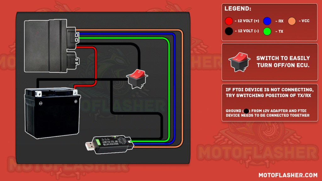
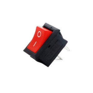
2. Add a switch between the 12V line going to the ECU to easily turn it ON/OFF during the flashing process.
3. Connect the TTL Device:
Black wire (GND) to the TTL and battery ground, add a switch that connects to ECU
Green wire (TX) and Yellow wire (RX) to the ECU’s respective TX and RX pins. (Follow the guide for correct pinout from our ecu pinouts page)
Brown wire (5V) can be used if your ECU requires 5V signaling
⚠️ Important: The ground from the battery and the TTL device must be connected together for proper communication.
This simple setup ensures reliable communication between your TTL device and the ECU for correct flashing procedure.
say hello toMotoFlasher V2
This release brings the latest updates and improvements, and introduces a subscription model. Lifetime users keep full access to all their existing add-ons when they subscribe, with no loss of previously purchased features.
Update now to get the newest version and continue using your add-ons without interruption.